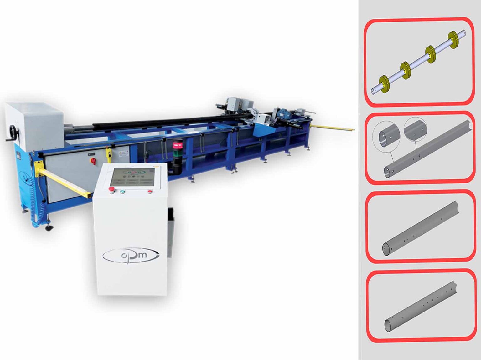
Working center / automatic machine for the drilling and working of roller shutter tubes / rolling shutter axes, is a working station designed for the production of rolling shutter tubes.
The work process consists of two phases: tube drilling and spring loading.
The system is designed and realized with the purpose of automating all operations on the tube, significantly reducing production times while achieving a high-quality product. The maximum workable tube length is 6 meters, with a projected productivity of 5 minutes for a finished tube with 4 boxes.
With the Real-Time graphical interface, the operator can preview the setup work process for roller shutter tubes on the monitor to avoid errors. The software with a graphical interface allows you to visualize and simulate the working process in the pre-production phase to confirm or modify the setup. User-friendly software enables setting the spacing between box holes and the spacing between the four motor holes (both right and left-hand), adapting to any motor type you intend to install.
The machine can store drilling measurements for the motors used and the measurements for drilling the boxes of roller shutter tubes. Once stored, the program recalls them based on the tube’s diameter.
The uniqueness of our machine lies in the precision of drilling that doesn’t deform the tube. The drilling units can create holes of various diameters for box fastening, motor attachment, and cable and brake passage. Central holes for box mounting are automatically threaded during the work process, creating a complete product.
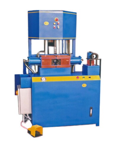
Our working center include also a punching working center (please ask for the specifical technical data sheet).
TECHNICAL FEATURES:
- Automatic machine for drilling roller shutter tubes / pipes / axes for rolling shutters of different lenght, for the realizing of spring boxes for rolling shutters
- Complete of electrical panel and dedicated system software for the complete managing of the production
- Electrical supply 4kW / 400 V
- Productivity : about 8 min for axe
- Workable Axes: Ø48 – Ø60 – Ø76 – Ø101
- Drills possible: M8 – Ø9 – Ø14
- Until 12 boxes for each axe
AUTOMATIC MACHINE FOR SHUTTER TUBES DESCRIPTION:
The Working center / automatic machine for the drilling and working of tubes / rolling shutter axes, compliant with CE regulations, consist of a base equipped with a headstock and tailstock, an electrically controlled rotating chuck, a hydraulic power unit, pneumatic and hydraulic systems, a 15’’ touchscreen PLC with software for managing and optimizing the work process, a punching unit, an electrically controlled mobile carriage with clamping clamp, a box locking system during the spring loading phase, and safety photocells.
Based on the feasibility study conducted, the work process consists of two phases: tube drilling and spring loading.
The operator places and clamps the pre-cut tube of the correct size on the machine and inserts its length into the machine.
Using the “automatic positioning” function, the machine, based on the tube’s length, determines the correct number of boxes and their positions to ensure the balance of the roller shutter.
With the Real-Time graphical interface, the operator can preview the setup work process on the monitor to avoid errors.
If the automatic positioning doesn’t meet the operator’s requirements, the machine allows manual positioning of the boxes.
The machine can store drilling measurements for the motors used and the measurements for drilling the boxes. Once stored, the program recalls them based on the tube’s diameter.
Within the software, you can store information for 8 different types of motors and their respective drilling measurements, allowing operators to use their preferred motors, whether right or left-handed (see attachment 2 and attachment 3).
Once the work process is set up in the PLC and the machine is started, the production occurs automatically. The machine positions itself for drilling by interpolating rotational and translational movements to maximize positioning speed. This, combined with simultaneous drilling from opposite sides, allows for rapid tube processing without deformation.
At this point, the PLC initiates the spring loading mode. The tube is re-secured between the headstock and tailstock, and the carriage automatically returns to its resting position. The operator positions the boxes over the previously drilled holes and secures the springs in the boxes using the M8 hole.
The operator configures the number of rotations for spring loading in the software and starts the winding phase. This includes an initial winding phase to fully load the springs into the boxes and a second phase for the actual spring loading, including the tensioning cycle.
Before locking the boxes onto the tube, you can verify the pulling force of each box using the LOAD CELL (optional), which reads the kg force each box exerts on the tube, allowing you to adjust the force based on the weight of the shutter being installed.
Subscribe to our You Tube page to be updated on the latest news: https://www.youtube.com/@OPMSTAMPI
